DENON DJ - MCX 8000
SETUP
Firmware & Drivers
Firmware : Update the firmware of the unit to the latest available version from https://www.denondj.com/downloads
Drivers : (Windows only) Download and install the latest Windows drivers from https://www.denondj.com/downloads . It is strongly advised to install drivers prior plugging the unit to a USB computer port.
No driver is necessary to be installed on Mac OSX computers.
VirtualDJ 8 Setup
Once VirtualDJ is opened, a Connect Window will appear. Login with your virtualdj.com account’s credentials.
A Pro Infinity or a Pro Subscription License is required to use the Denon DJ MCX-8000. Without any of the above Licenses, the controller will operate for 10 minutes each time you restart VirtualDJ.
https://www.virtualdj.com/buy/index.html

Click on the MCX8000 button in order VirtualDJ to apply the pre-defined audio configuration (speakers need to be connected to the rear side of the unit in this case)
Click to OK
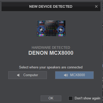
The unit is now ready to operate.
MIDI Operation
The unit should be visible in the MAPPING tab of Config as 3 devices (Denon DJ MCX8000 for the main unit and 2 more for the Left and Right LCD Displays) and the “factory default” available/selected from the Mappings drop-down list for all 3 of them.
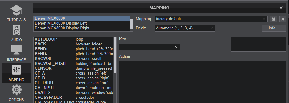
The factory default Mapping offers the functions described in this Manual, however those can be adjusted to your needs via VDJ Script actions.
Find more details at http://www.virtualdj.com/wiki/VDJ8script.html
Note : If the LCD screens are inverted (i.e. the Left LCD screen shows the info of the right deck and vice versa), make sure the Display Left unit is assigned to Decks 1,3 and the Display Right unit is assigned to Decks 2,4.
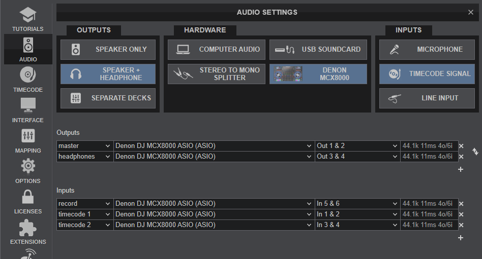
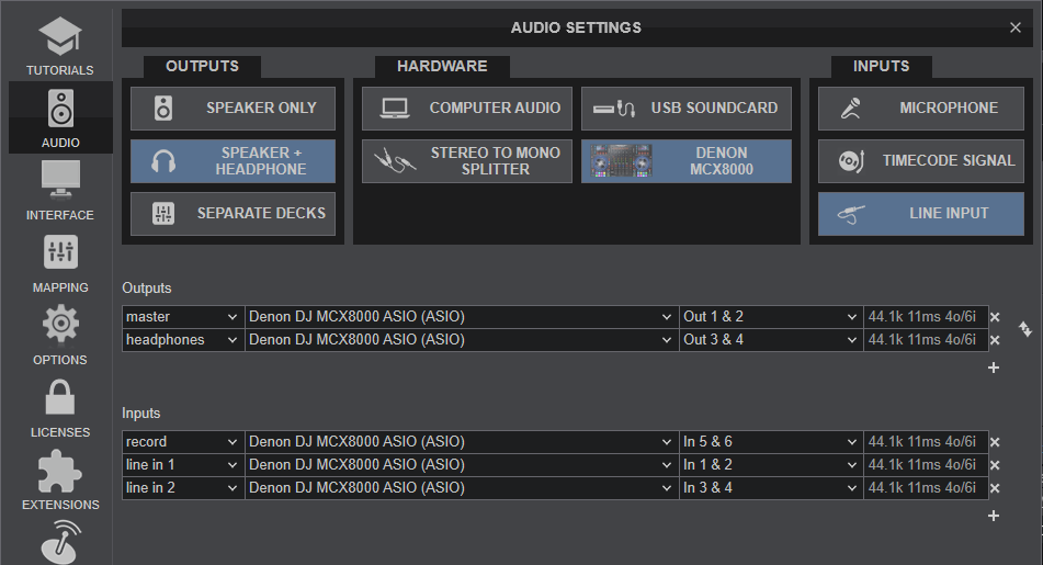
AUDIO Setup
The unit has a pre-defined Audio setup and a special button in the AUDIO tab of Config to provide that.
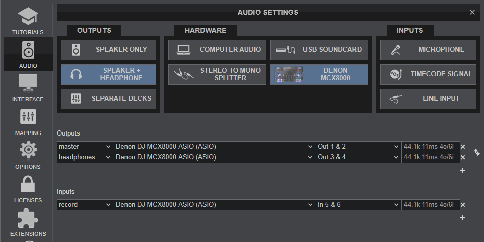
See also Inputs & Recording.
For further software settings please refer to the User Guide of VirtualDJ .
https://www.virtualdj.com/manuals/virtualdj8/index.html
LAYOUT
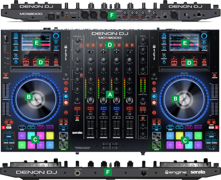
The functionality of each button, knob and connection per section (as shown in the image above) will be explained in detail in the next chapters
S SHIFT: Press and hold this button to access secondary functions of other controls on the MCX8000
A Mixer Controls
B Deck Controls
C Pads
D Effects
E Browser & Screens
F Front & Rear
MIXER CONTROLS
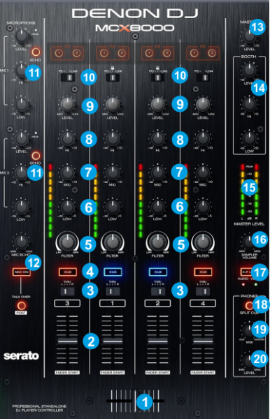
- CROSSFADER. Blends audio between the channels assigned to the left and right side of the crossfader.
- VOLUME. Volume Faders (mixer channel order is 3-1-2-4 decks). Note that the faders will not to alter the sound of the corresponding software deck, if the PC-LINE switchers are on LINE or ENGINE positions, and the sound of the software decks will be muted.
Hold SHIFT down and then use the Volume Faders to start/stop the deck when moving from the minimum to any other position (Fader Start/Stop) - CF ASSIGN. Use these switchers to assign each mixer channel to a side of the Crossfader. Select the L (Left) or R (Right) position to assign a deck to the left or right side of the crossfader. When in Thru position, the crossfader will not affect the output level of the mixer channel.
- CUE/PFL. Use these buttons to send one or more channel's pre-fader signal to the Cue Channel for monitoring. When engaged, the buttons will be lit (orange for decks 3 and 4 and blue for decks 1 and 2).
- FILTER. Applies a High/Low-pass Filter on each channel.
- EQ LOW *. Adjusts low (bass) frequencies of the corresponding channel in the software or hardware Input.
- EQ MID *. Adjusts the middle (mid) frequencies of the corresponding channel in the software or hardware Input.
- EQ HI *. Adjusts the high (treble) frequencies of the corresponding channel in the software or hardware Input.
- LEVEL. Adjusts the audio level (gain) of the corresponding channel in the software or hardware Input.
- INPUT SELECTOR. Set this switch to the desired audio source for each mixer channel:
- PC (a track playing on that layer in VirtualDJ), Set all 4 switches to PC position in order to control 4 VirtualDJ decks.
- LN1/2/3/4 (a device connected to the Line Inputs on MCX8000 rear panel).
- ENGINE (available for Channels 1 and 2) Track playing from the USB 1/2 Source using the Engine software.
Note: the software deck will be muted if the switcher is on LINE or ENGINE positions. - MIC1/MIC2. Adjusts the Level, High and Low frequencies of each Microphone Input (connections at the rear panel). Use the ECHO button to apply an Echo effect to the each one of the Microphone signals. This section is completely working on the Hardware side, so there is no feedback to the software, and the Microphone Inputs are not part of the USB Audio interface either.
- MIC ECHO/ON/POST. Use the MIC ECHO knob to adjust the amount of the Echo effect applied on both the Microphone signals. Use the MIC ON button to turn on/off both Microphone inputs. Use the TALKOVER button to automatically reduce the Master Output level when signal is detected on the Microphone inputs. Hold SHIFT and then use the same button (POST) to output the Microphone Input signals to the Booth Output only.
- MASTER LEVEL Adjusts the output level of the Master Output (connection at the rear panel). Independent Hardware operation, not controlling VirtualDJ Master Output nor its movement is visible on VirtualDJ GUI
- BOOTH LEVEL/HI/LOW Adjusts the output level of the Booth Output (connection at the rear panel) and apply Hi/Low Equalizer adjustments. Independent Hardware operations, not controlling VirtualDJ mixer nor their movements are visible on VirtualDJ GUI
- MASTER VU METER Indicate the output level of the Master Output. Independent Hardware operation, not reflecting VirtualDJ Master VU Meter of VirtualDJ GUI
- SAMPLER VOLUME Adjust the Master Volume of the VirtualDJ Sampler
- XF-LINK Use this button to Link/Un-Link Video Crossfader with Audio crossfader. When the green LED is turned on, the Video Crossfader will follow the position of the Audio Crossfader (Linked).
Hold SHIFT and then use the same button to disable the Audio Crossfader (Video Crossfader will still be controlled by the X-Fader if the green LED is turned on. The red LED will be off f the Audio Crossfader is disabled. - SPLIT CUEUse this button to send Master Output signal to one side of the Headphones and the CUE/PFL channels to the other one.
Independent Hardware operation, not controlling VirtualDJ Split Cue setting - PHONES MIX Use this knob to blend Master Output signal with the Channels that have the CUE/PFL buttons enabled. When the knob is at the minimum position, only audio coming from the channels that have CUE/PFL enabled will be sent to Headphones. When in maximum position only audio signal from Master Output will be sent to the Headphones channel.
Independent Hardware operation, not controlling VirtualDJ Headphones Volume knob nor its movement is visible on VirtualDJ GUI - PHONES LEVEL Adjust the Volume of the Headphones Channel.
Independent Hardware operation, not controlling VirtualDJ Headphones Mix knob nor its movement is visible on VirtualDJ GUI
* Note: The device is offering Full Stems controls. See details at EQ Modes
DECK CONTROLS
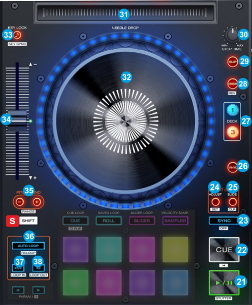
- SSHIFT: Press and hold this button to access secondary functions of other controls on the MCX8000
- PLAY. Plays / Pauses the track. Hold SHIFT down and then press this button to "stutter-play" the track from the last set Cue Point.
- CUE. When the Deck is paused, you can set a temporary Cue Point by moving the Platter to place the Audio Pointer at the desired location and then pressing the Cue Button.
During playback, you can press the Cue Button to return the track to this Cue Point. (If you did not set a Cue Point, then it will return to the beginning of the track.).
If the Deck is paused, you can press and hold the Cue Button to play the track from the Temporary Cue Point. Releasing the Cue Button will return the track to the temporary Cue Point and pause it.
To continue playback without returning to the Temporary Cue Point, press and hold the Cue Button, then press and hold the Play Button, and then release both buttons.
Press and hold SHIFT and then press this button to return to the beginning of the track. - SYNC. Press this button to automatically match the corresponding Deck's tempo and phase with the opposite Deck's (or the Master Deck’s if using a 4 decks Skin) tempo and phase. Hold SHIFT down and then press this button to set this deck as Master Deck. While SHIFT is held down, the Master Deck's SYNC button will be lit.
When the LED blinks, it means that the manual Master Deck selection mode is active (i.e. you had manually selected the Master Deck). Press the flashing button to revert back to the Auto-selection Master DEck mode and let VirtualDJ to decide which Deck is Master mostly based on the deck that is playing out live. - BEATGRID ADJUST. Press this button to enter jogwheel to BeatGrid Adjust mode (led will blink). While this mode is enabled, use the Jogwheel to adjust the width of the Beatgrid pattern which is equal to adjusting the BPM. Once the adjustment is made, press again to exit this mode.
Hold SHIFT down and then press this button to set the Beat-grid anchor (First Beat) to the current track's position. - BEATGRID SLIDE. Press this button to enter jogwheel to BeatGrid Slide mode (led will blink). While this mode is enabled, use the Jogwheel to move Beatgrid pattern forward/backwards in time. Once the adjustment is made, press again to exit this mode.
Hold SHIFT down and then press this button to undo all manual edits and VirtualDJ to re-analyze the track.. - VINYL. Press this button to set the Jogwheel to Vinyl (Scratch) or CD (Bend) mode. In Vinyl mode, use the outer part of the Jogwheel to bend (temporary speed up – slow down the tempo of the track).
- DECK SELECT. Use these buttons to select which software Deck each side of the unit will control. The Left side can control wither Deck 1 or Deck 3. Right side can control either Deck 2 or Deck 4.
- CENSOR. Press this button down to play the track in reverse. When the button is released, the track will continue playing from the position it would have been if never used (CENSOR)
Hold SHIFT down and then press this button to play the track in reverse mode. - SLIP. Press this button to enable/disable Slip mode. When enabled, several actions like scratching, Hotcues, Loops etc will act temporary, and the track will resume playing from the position it would have been if the action was never triggered.
- STOP TIME. Use this knob to define the time needed for the track to completely stop when paused (Vinyl Brake emulation). Set the knob to the minimum position for instant pause.
- NEEDLE DROP. Touch-strip for track's search. For security reasons, the strip will not have any effect when the track is audible (track is playing and its Channel Fader is away from the minimum position).
Hold SHIFT and then use the same touch-strip to navigate through the track regardless the track's playing/audible status. - JOG. Touch sensitive jogwheel. Use the jogwheel to scratch (if Vinyl mode is selected) or pitch bend. The Jogwheel also offers Loop In and Loop Out point adjustment (see further down in Loops keys)
Hold SHIFT and then use the Jogwheel to fast search through the track. The difference between the Jogwheel Search and the Needle drop,, is that the search with the Needle Drop always keeps the track on beat.
Jogwheel is also used to adjust Beatgrid when the Beatgrid Adjust or Slide mode is enabled.
The LEDs around the jogwheel can have 2 kind of patterns, one with a single chasing LED ON and a second one with a single chasing LED OFF. Choose your favorite pattern for each one of the 4 available decks via the Utilities menu of the unit (hold down the UTILITIES button for more than 1 second to access the menu) - KEYLOCK. Press this button to "lock" the track's pitch to its original key. The track's tempo will remain at the speed designated by the Pitch Fader.
Hold SHIFT down and then use this button to match deck's key with the key value of the opposite deck - PITCH. Adjust the track's playback speed (tempo). When pitch is at the middle position (track is playing at its original speed), the green LED will be lit.
When the orange LEDs are lit, the pitch fader has to be moved to the direction the arrows indicate, in order to catch the pitch value of the deck. This is mostly happening when decks are swapped (via the DECK SELECT buttons) and the pitch value of one deck is different than the other.
Note that this Hardware-takeover is not following the soft-takeover of VirtualDJ, meaning that if SHIFT is pressed, the arrows will not indicate the direction the pitch fader needs to be moved to in order to re-gain pitch control, but the ghost-fader on the GUI will be an aid. - PITCH BEND. Press and hold these buttons down to temporary speed up/slow down the song while pressed. When released, the track playback will return to the speed designated by the Pitch Fader.
Hold SHIFT down and then use this button to select the previous/next available % range of the Pitch Fader - AUTOLOOP. Press this button to trigger or exit a seamless Loop of the selected size in Beats
Hold SHIFT and then use this button to enable the last triggered Loop (Re-Loop) - LOOP x 1/2. Press this button to half the size of the Loop
Hold SHIFT down and then use this button to set current position as the Start point (Loop In) of a manual loop. When a Loop is enabled, press this button to set Jogwheel to Loop In Adjust mode and use the Jogwheel to fine adjust the position of the Loop In point in time. Hold SHIFT and then press again to exit this mode. Loop In Adjust mode will still exit if the Loop is disabled via the AUTOLOOP button. - LOOP x2. Press this button to double the size of the Loop
Hold SHIFT down and then use this button to set current position as the End point (Loop Out) of a manual loop. When a Loop is enabled, press this button to set Jogwheel to Loop Out Adjust mode and use the Jogwheel to fine adjust the position of the Loop Out point in time. Hold SHIFT and then press again to exit this mode. Loop Out Adjust mode will still exit if the Loop is disabled via the AUTOLOOP button.
PADS
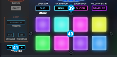
Pads (40) offer 10 different modes, depending on the PAD MODE SEL buttons (39). Press the same PAD MODE button again to access the additional mode (the LED will get a different color). Hold SHIFT and then press the CUE or SAMPLER mode buttons to get 2 additional modes.
Each time a mode is selected, a Page will be selected and displayed on the Pads section of the default VirtualDJ skin
Note: The ROLL and SLICER pad modes don't offer any additional mode if SHIFT is pressed.
Use the PARAMETER < > buttons (41) to adjust the Parameter 1 (if available) of the selected Pads page
Hold SHIFT down and then use the PARAMETER < > buttons (41) to adjust the Parameter 2 (if available) of the selected Pads page
HotCues mode
Press the CUES mode button to set the PADs to HotCue mode (LED will be lit blue). The Hotues page will be then selected and displayed on the Pads section of the VirtualDJ skin
Each one of the 8 pads assigns a Hot Cue Point (1 to 8) or returns the track to that Hot Cue Point.
When a Hot Cue Button is unlit, you can assign a Hot Cue Point by pressing it at the desired point in your track. Once it is assigned, the Hot Cue Button will light up.
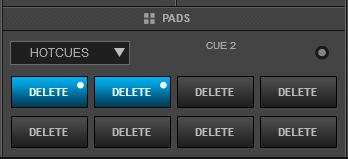
Hold SHIFT and then press any of the pads to delete its assigned Hot Cue Point.
Use the PARAMETER < and > buttons (41) to jump to the next or previous HotCue.
Hold SHIFT down and then use the PARAMETER <> buttons to jump the track forward/backwards by 1 beat
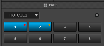
Note: By default Hotcues will get the color of the deck (blue for deck 1, red for deck 2, green for deck 3 and orange for deck 4). A different coloring behavior can be offered via the NonColoredPOI setting (from VirtualDJ Settings OPTIONS tab).
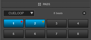
Cue-Loop mode
Press the CUES Mode button twice (or once if the selected mode was HotCues) to set the Pads to HotCue Loop mode (the led of the CUES button will be lit green). The CueLoop page will be then displayed on the Pads section of VirtualDJ skin
Each one of the 8 Pads assigns a Hot Cue Point or returns the track to that Hot Cue Point, but in both cases, it also triggers a momentary or toggle Loop depending on the selected mode.
The currently selected length will be used for the triggered Loop
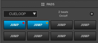
Hold SHIFT down and then press a pad to jump to the Hot Cue Point but leave the Loop enabled.
Use the PARAMETER < and > buttons (41) to half and double the size of the applied Loop.
Hold SHIFT down and then use the PARAMETER < > buttons to select the On/Off (toggle) or Hold (loop will be enabled while the Pad is pressed) mode
Loop Roll mode
Press the ROLL mode button to set the Pads to Loop Roll mode (LED will be lit cyan). The LOOP ROLL page will be then selected and displayed in the Pads section of the default VirtualDJ skins.

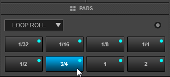
Each one of the 8 Pad triggers a momentary Loop Roll (while pressed) of a different length in beats as per the images above.
In this mode the PARAMETER (41) buttons have no functionality.
Saved Loops mode
Press the ROLL Mode button twice (or once if the selected mode was Loop Roll) to set the Pads to Saved Loops mode (the led of the ROLL button will be lit yellow). The Saved Loops page will be then selected and displayed in the Pads section of the VirtualDJ skins.
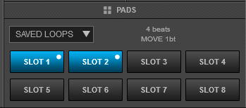
This mode offers the ability to save up to 8 Loops to individual Loop Slots.
Press any Pad to save the current Loop at the current track’s position (of the selected size in beats) to the relative slot. Hold the same Pad down for more than 1 second to delete the Saved Loop.
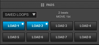
When a Loop slot is saved, press the corresponding Pad to load (prepare) the Saved Loop.
If the track’s position is before the Saved Loop point, the loop will be enabled but the track will not jump to that position (Prepare status). Use the same Pad to disable the Loop.
Hold SHIFT down and then press one of the lower Pads to load the Saved Loop, but also jump to that position.
Use the PARAMETER < and > (41) buttons to half and double the size of the triggered Loop.
Hold SHIFT down and then use the PARAMETER buttons to move the Loop forward/backwards by 1 beat
Slicer mode
Press the SLICER mode button to set the PADs to Slicer mode (LED will be lit red).The Slicer Page will be then selected and displayed in the Pads section of VirtualDJ skin.
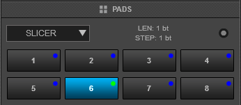
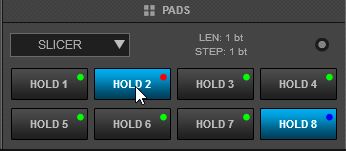
The eight pads represent eight sequential beats/Slices in the Beat Grid. The playing Slice is represented by the currently green lit pad. The green light will "move through the pads" as it progresses through each eight-Slice phrase. Press a pad to repeat that Slice (hold it down if you want to keep looping it). Once the Pad is released the track will continue to play from the position it would have been if the pad was never pressed.
Hold SHIFT button down and then use the same Pads to use the Slicer in Hold mode. In this mode, the slices are memorized (using the last triggered ones)
Use the PARAMETER < and > buttons (41) to adjust the length of the Loop applied to the slice. Press SHIFT and then use the same PARAMETERS < and > buttons to adjust the step of the Slices.
Beatjump mode
While the Slicer mode is selected, press the same SLICER mode button again to set the PADs to Beat Jump mode (led will blink). The BeatJump page will be then selected and displayed on the Pads section of the VirtualDJ skin
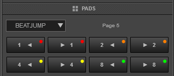
In this mode, each one of the Pads will jump the track backwards/forward by the amount of beats depending on the selected page/bank (from 1/8 beats to 32 bars)
Use the PARAMETER < > buttons to select a different bank/page with the desired size of beat jumps
Sampler mode
Press the SAMPLER mode button to set the PADs to Sampler mode (LED will be lit magenta). The Sampler Page will be then selected and displayed in the Pads section of the VirtualDJ default skins
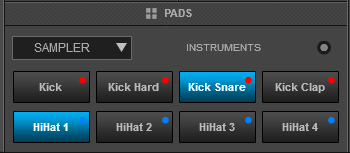
Each one of the 8 pads triggers a sample (1 to 8) from the selected Sampler Bank of VirtualDJ. If the selected Sampler Bank has less than 9 samples, both sides of the unit will trigger the same Samples. If the selected Sampler Bank has more than 8 samples, the left side of the unit will trigger Samples 1 to 8 and the right side of the unit will trigger Samples 9 too 16.
The leds of the Pads will automatically get the assigned color of each sample (dark when off, bright when playing).
Press the pads to trigger a sample. Depending on the selected trigger mode, use SHIFT and the same pads to stop the sample.
Use the PARAMETER < and > buttons (41) to select the previous and next Sampler Bank.
Hold SHIFT down and then use the same PARAMETERS buttons to select the previous/next Trigger Pad mode (on/off, hold, stutter, and unmute)
Sampler Velocity mode
While the Sampler mode is selected, press and hold down the same SAMPLER mode button for more than 1 second to to enable/disable Sampler Velocity mode (led will be lit purple).
When enabled, each one of the 8 pads triggers a sample (1 to 8) from the selected Sampler Bank of VirtualDJ, with the difference that the Output Volume of each sample is determined by the strength the Pad was initially pressed.
Tip: To return all samples to their maximum values after the Velocity mode is used, select the next or previous available bank and then select the current again.
Remix Points mode
Hold SHIFT down and then press the CUES mode button to set the PADs to Remix Points mode (led will be lit red). The Remix Points Page will be then selected and displayed in the Pads section of the VirtualDJ default skins
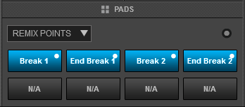
This mode offers the first 8 Remix Points of the loaded track. Remix Points are automatically defined from VirtualDJ, once the track is analyzed. Remix points can be managed from the POI Editor (more can be added/adjusted/deleted). They usually represent End/Start points of track’s blocks depending on the structure of the track and are always quantized when triggered.
The Remix points will be visible on the Song-position progress of the GUI (with white markers) once the Remix Points Pad page is selected.
Key - HotCue mode
Hold SHIFT down and then press the SAMPLER mode button to set the PADs to Key - Hotcue mode (led will be lit green). The KeyCue Page will be then selected and displayed in the Pads section of the VirtualDJ default skins
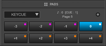
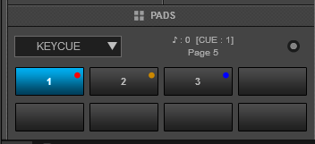
In this mode, the Pads trigger a selected Hotcue point (or the Temporary Cue if none selected or not available) at a selected Key semitone (from -7 to +7).
8 different pages/banks are offered with various semitone values to use and a 0 value (reset key to tis original value) is always offered in all pages.
Hold SHIFT and then select a Hotcue for the Key pads to trigger. Each time a Pad is pressed, the track will jump to that Hotcue point and will also alter the Key of the track to the value designated by it assigned value.
Use PARAMETER buttons <> to adjust the Key of the track without trigger a Hotcue.
Hold SHIFT and then use the PARAMETER buttons to select a different page/bank with different key semitone values.
MCX8000 Browser mode
A special MCX8000 page is also available when the MCX8000 is connected. The page can be selected from the drop-down list of the GUI.
This special page will provide the ability to adjust the content of the Browser columns on the LCD screens. The selections are saved across sessions and only apply to the Browser view of the MCX8000 Displays and not the Browser of VirtualDJ.
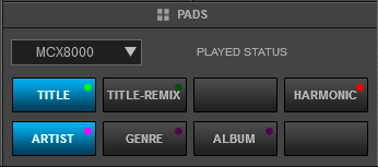
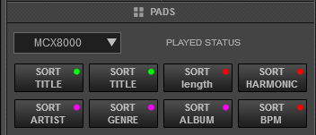
Use Pads 1 or 2 (green pads) to display Title or Title (Remix) at the 1st column of the Files Browser view on the LCD screens of the unit
Use Pads 5, 6 or 7 (purple pads) to display Artist, Genre or Album for the 2nd Column of the Files Browser view
Use Pad 4 (red pad) to display Harmonic, Key or Key Difference for the 3rd Column of the Files Browser view when the Key column is selected (via SHIFT+VIEW button)
Hold SHIFT down and then use the Pads to sort Columns 1, 2 and 3 alphabetically in ascending or descending order, depending on the selected field of each Column.
Use PARAMETER buttons <> to choose between displaying the Tracks with the assigned colors, or displaying Played tracks in red and un-played tracks in white.
Notes :
- The MCX8000 can be only selected from the Pads Page drop-down list of the GUI, but you may also assign any button as pad_page 'MCX8000' to perform this action
- The actions assigned to the Pads of this page, can be controlled from both the GUI and the MCX8000 Pads.
EFFECTS
Each one of the left/right FX unit offers 2 modes. The Single Effects mode offers one effect slot but more parameters controls. The Multi Effects mode offers 3 effect slots (to trigger more than 1 effect at the same time – chained effects). The selection between those 2 modes is done by pressing the TAP (48) button while SHIFT is held.
Most of the Effect Info andParameters will be also displayed on the LCD Screens of the unit.
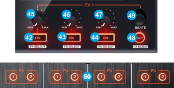
Single FX mode
Hold SHIFT down and then use the TAP (48) button to select the Single FX mode in the default GUI. The Single FX mode is selected by default on first launch
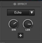
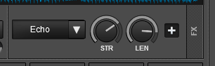
In this mode a single Effect is controlled with up to 6 Parameters and 4 Effect buttons. Only the first 2 Parameters are visible on the GUI. More Parameters and Effect buttons can be viewed in the FX GUI (opened from the + button on the GUI)
- FX1 ON. Press this button to enable/disable the selected effect to the Left/Right selected deck.
Hold SHIFT down and then use this button, to select the next available Effect. - FX2 ON. Press this button to enable/disable the 1st effect button of the selected effect (if available).
Hold SHIFT down and then press this button to enable/disable the 3rd effect button of the selected effect (if available). - FX3 ON. Press this button to enable/disable the 2nd effect button of the selected effect (if available).
Hold SHIFT down and then press this button to enable/disable the 4th effect button of the selected effect (if available). - FX1 knob. Controls the 1st effect parameter of the selected effect.
Hold SHIFT down to control the 4th effect parameter of the selected effect (if available). - FX2 knob. Controls the 2nd effect parameter of the selected effect.
Hold SHIFT down to control the 5th effect parameter of the selected effect (if available). - FX3 knob. Controls the 3rd effect parameter of the selected effect.
Hold SHIFT down to control the 6th effect parameter of the selected effect (if available).
Multi FX mode
Hold SHIFT down and then use the TAP (48) button to select the Multi FX mode in the default GUI.
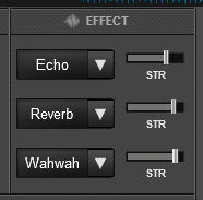
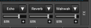
In this mode 3 different Effects can be applied and controlled with up to 2 Parameters for each FX slot. Only the first Parameter is visible on the GUI (and the 2nd Parameter while SHIFT is held on the MCX8000). More Parameters and Effect buttons can be viewed in the FX GUI (opened from the + button on the GUI)
- FX1 ON. Press this button to enable/disable the selected effect of FX slot 1.
Hold SHIFT down and then use this button to select the next available Effect for the 1st Effects Slot - FX2 ON. Press this button to enable/disable the selected effect of FX slot 2.
Hold SHIFT down and then use this button to select the next available Effect for the 2nd Effects Slot - FX3 ON. Press this button to enable/disable the selected effect of FX slot 3.
Hold SHIFT down and then use this button to select the next available Effect for the 3rd Effects Slot - FX1 knob. Controls the 1st parameter of the selected effect of FX slot 1.
Hold SHIFT to control the 2nd parameter of the selected effect of slot 1. - FX2knob. Controls the 1st parameter of the selected effect of FX slot 2.
Hold SHIFT to control the 2nd parameter of the selected effect of slot 2 - FX3 knob. Controls the 1st parameter of the selected effect of FX slot 3.
Hold SHIFT to control the 2nd parameter of the selected effect of slot 3.
OTHER FX KEYS
- TAP Press this button repeatedly on beat (for at least 4 times) to manually tap the tempo of the track. When track is paused, press this button to set the current track's position as First Beat Anchor.
Hold SHIFT down and then this button to toggle between the Single and Multi Effect modes. - BEATS Use this encoder to increase/decrease the value of the Beats for the selected Effect (in case the Effect offers such a feature).
Push the encoder to set the value to 1 beat
Hold SHIFT down and then use this encoder to move the key of the track forward/backwards by 1 semitone.
Hold SHIFT down and then push the encoder to reset the Key of the track to its original value - FX ASSIGN Use these buttons to clone (copy) the Effects and their Parameter values from one deck to the other.
E.g. when FX2 is pressed on CH3 on the mixer, the Effects from Deck 2 are copied to Deck 3 or when SHIFT+FX1 is pressed on CH4, the Effects from Deck 3 will be copied to Deck 4
BROWSER & SCREENS
- SELECT/LOAD. Use this encoder to scroll through tracks or Folders.
Push the encoder to load the selected track to the Deck. If the focus is on the Folders list, push the encoder to set focus to the Songs List.
Hold SHIFT and then push the encoder to toggle between the Normal and Browser Zoom (with Midi decks) view. This function only affects the Browser of the VirtualDJ GUI and not the screens
The LED of this encoder will be off when no track is loaded, on when a track is loaded and will blink if the track reaches 30 seconds before its end. You can turn on/off the blinking behavior using SHIFT+TIME - BACK. Press this button to set focus to the Folders Browser window and display the Folders view on the screen. If focus is already set to the Folders list, the button will expand/collapse sub-folders
Hold SHIFT down and then press this button to forward cycle through the available Browser windows (Folders, Songs, Sideview) - LOAD PREP. Press this button to load the selected track from the Songs List to the Automix List of the Sideview
Hold SHIFT down and then press this button to open/close Sideview - VIEW. Press this button to toggle between the Browser and the Deck view of the screen. The Browser view will be automatically offered when any Browse, Browser Window or other Browser functions are triggered and will automatically return to the Decks view after 5 seconds if no Browser action is triggered or immediately after a track is loaded.
Hold SHIFT down and then use this button to choose what the 3rd column of the screen will display (BPM, Key or Track Length) - CRATES. Set focus to the Sideview of Browser. The selected Sideview List will be also displayed on the LCD screen
Hold SHIFT down and then press this button to cycle through the available Lists of Sideview (Automix, Sidelist, Karaoke, Sampler and Clones) - ZOOM IN/OUT. Use this button to increase the Zoom level of the waveform. Hold SHIFT down to decrease the zoom level. 4 Zoom levels are available
- SINGL/CONT. Enables/disables Automix on this deck.
Hold SHIFT and then use this button to enable/disable Load Security. When enabled, loading tracks to a deck that is audible and playing will have no affect and will be ignored. - TIME. Use this button to toggle displayed track's time between Elapsed and Remained.
Hold SHIFT down and use this button to turn on/off the blinking of the SELECT/LOAD Led when track reaches its end. - LCD. 5" RGB screen. Displays various Track's info, Browser view, waveforms etc. See details below
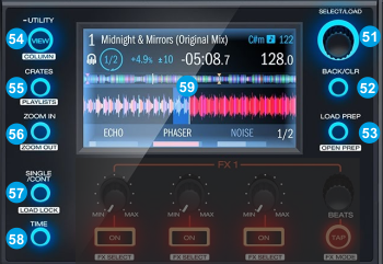
Display
MCX8000 full-color displays provide real-time feedback of the software with 2 available views, Performance View, and Browser View.
Use the VIEW button to toggle between the views. To enter Browser View immediately, turn the SEL Knob (60) or any other button that offers a Browser function such as the CRATES, LOAD PREP or BACK
The Browser view will be kept on sight for at least 5 seconds if no Browser related button is used. The Performance view will be also automatically displayed when a track is loaded..
Each view shows the current settings of various controls, which you can adjust as described in the following sections.
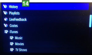
(Library – Folders List)
(Library – Songs List)
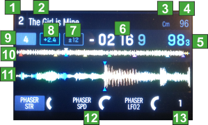
1Deck: Indicates the number of the currently left/right selected deck of VirtualDJ controlled by the left/right side of the unit. Use the DECK select buttons to switch between the decks.
2Track Name: Displays the Title of the currently loaded track.
3Track BPM: Displays the original tempo (in beats per minute aka BPM) of the currently loaded track with a 0% pitch adjustment. To see the BPM at which it is currently playing, see Deck BPM below.
5Deck BPM: Displays the current BPM at which the currently loaded track is playing. To adjust this value, move the deck's Pitch Fader. This number is not affected by temporary pitch bends (using the Pitch Bend -/+ buttons or the platter).
6Time: Displays how much time is left or spent of the currently loaded track. Use the TIME button to toggle between remained and elapsed Times. Note that the displayed time is not taking the pitch into account (absolute value), so if the tempo is not the original, the time will differ from the one that is displayed on the Skin.
7Pitch Range: Displays the currently selected range of the Pitch Fader. Use SHIFT + PITCH BEND buttons to select a different % range
8Pitch Value This is the current setting of the Pitch Fader. To adjust this setting, move the deck's Pitch Fader.
9Loop box Indicates the currently selected Loop size in beats. the box will become blue if a Loop or a Loop Roll is enabled
10Track Progress bar: This is the currently loaded track's waveform, which is color-coded according to the frequency of each area: red indicates low (bass) frequencies, green indicated mid-range frequencies, and blue indicates high (treble) frequencies.
In the waveform, hot cue points are represented by triangles at the bottom of the waveform and loop regions are represented by shaded-blue sections.
11Waveform: This is the currently playing segment of the track's waveform, which will scroll by as the audio play-head moves through the track. The waveform is color-coded according to the frequency of each area: red indicates low (bass) frequencies, green indicated mid-range frequencies, and blue indicates high (treble) frequencies. In the waveform, hot cue points are represented by triangles at the top and bottom of the waveform, and loop regions are represented by shaded-blue sections.
12Effects Info. Displays the names of the selected Effects and their Parameters, following exactly the functionality described in the Effects section.
13Effect Beats: Indicates the Effect Beats for the selected Effect (FX1 Slot if the Multi FX mode is selected) and will display 1/32 if the selected Effect does not support this feature.
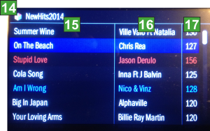
14Folders names Displays the name of the selected folder. In Songs List view, if the Sideview is selected, the name of the selected view will be displayed.
15Track's Title Displays the title of the track. Title (Remix) format can be also selected via Pads - MCX8000 page
16Track's Artist Displays the Artist of the track. Album and Genre can be also displayed via Pads - MCX8000 page
17Track's BPM By default displays the BPM of the track. Length and Key can be also displayed by holding SHIFT down and useing the VIEW button. If the Key column is selected, Harmonic and Key Difference can be also displayed. See Pads - MCX8000 page
FRONT & REAR PANELS
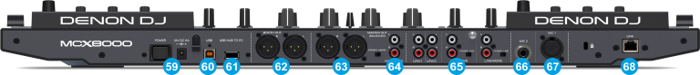
- POWER: Use the included AC/DC power suplier to connect MCX8000 to a power outlet. While the power is switched off, plug the cable into unit first, and then plug the cable into a power outlet. Use the Power Switch to turn the unit on and off. Turn on unit after all input devices have been connected and before you turn on amplifiers. Turn off amplifiers before you turn off unit
- USB. Connect the unit with a USB port of your computer using the provided USB cable. This USB connection sends and receives audio and control information from a connected computer.
- USB HUB. Use the USB HUB socket to connect other USB devices that need to be connected to your computer.
- BOOTH OUT (XLR): Use XLR cables to connect this output to a booth monitoring system. The level of this output is controlled by the Booth section on the top panel.
- MASTER OUT (Balanced - XLR): Connect this low-impedance XLR output to a PA system or powered monitors. The level of this output is controlled with the Master Level knob on the top panel.
- MASTER OUTPUT (RCA): Use standard RCA cables to connect this output to a speaker or amplifier system. The level of this output is controlled by the Master Level knob on the top panel.
- LINE INPUTS. Connect your audio sources to the 4 available LINE inputs. LINE Inputss 3 and 4 can accept both line and phono-level signals and can be used for DVS as well (see Inputs & Recording. ). Use the PC/ENGINE/LN switches at the top panel to send the audio signal of these Inputs to a Mixer Channel.
- MIC 2 Connect a microphone to this input using a 1/4" cable. This input's audio signal is routed directly to the Program Mix and Cue Mix. The Microphone audio signal is controlled from the top panel
- MIC 1. Connect a microphone to this input using a 1/4" or XLR cable. This input's audio signal is routed directly to the Program Mix and Cue Mix. The Microphone audio signal is controlled from the top panel
. - LINK
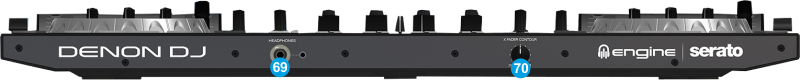
- XFADER CURVE. Adjusts the slope of the crossfader curve. Turn the knob to the left for a smooth fade (mixing) or to the right for a sharp cut (scratching). The center position is a typical setting for club performances.
- HEADPHONES SOCKET. Connect your 1/4" or 1/8" headphones to this output for cueing and mix monitoring.
INPUTS & RECORDING
The Denon DJ MXC8000 offers a variety of Inputs and Operation modes. The unit can operate as a stand-alone mixer and playback audio from either an analogue media source (CD Player, Turntable etc) connected to one of the 4 available LINE Inputs at the rear panel or digital media from a USB device connected at the right-top panel via the integrated Engine application. Along with the ability to use a Computer DJ Application, the MCX8000 provides a variety of tools to the user.
MIXER CHANNELS
Channel 3 (far left) : Audio signal from an analogue source connected to the LINE 3 at the rear panel can be inserted and processed by the mixer when the switcher at the top panel is set to LN3 position
Audio signal from VirtualDJ Deck 3 can be routed to this Channel when the switcher at the top panel is set to PC position
Channel 1 (middle-left) : Audio signal from an analogue source connected to the LINE1 at the rear panel can be inserted and processed by the mixer when the switcher at the top panel is set to LN1 position
Audio signal from a digital source connected to the USB ports at the right-top panel can be inserted and processed by the mixer and the side decks via the integrated Engine application, when the switcher at the top panel is set to ENGINE position
Audio signal from VirtualDJ Deck 1 can be routed to this Channel when the switcher at the top panel is set to PC position
Channel 2 (middle-right) : Audio signal from an analogue source connected to the LINE2 at the rear panel can be inserted and processed by the mixer when the switcher at the top panel is set to LN2 position
Audio signal from a digital source connected to the USB ports at the right-top panel can be inserted and processed by the mixer and the side decks via the integrated Engine application, when the switcher at the top panel is set to ENGINE position
Audio signal from VirtualDJ Deck 2 can be routed to this Channel when the switcher at the top panel is set to PC position
Channel 4 (far right) : Audio signal from an analogue source connected to the LINE 4 at the rear panel can be inserted and processed by the mixer when the switcher at the top panel is set to LN4 position
Audio signal from VirtualDJ Deck 4 can be routed to this Channel when the switcher at the top panel is set to PC position
Notes :
- Each time a different source is selected from the top switchers, the audio signal of other sources on the same channel will be muted.
- Switch between various sources is smooth, providing the ability of back-to-back dj changeover. E.g. while VirtualDJ is used from one dj, the 2nd DJ can use Engine (USB stick) or an analogue media source (e.g. a Cd Players) to play a track until the first computer is disconnected from the USB and the 2nd one to be plugged.
Recording & Broadcasting
The unit offers the ability to record the Master Output along with the Microphone and LINE Inputs directly from VirtualDJ record button (in the MASTER center panel). The dedicated Recording input channel is already pre-configured, so no further adjustments need to be done.

You will probably find the recording level quite low though, so you may want to increase the USB output level sent from the MCX8000, by visiting the UTILITIES of the unit.
Hold down the UTILITY/VIEW button, locate the USB Output Level setting and change it from the default 0db to around 10db.
Note : The recorded output includes any source routed to the Mixer, including media played via the Engine application or other analogue media sources connected to the LINE Inputs when the top switchers are set to the relative position.
Timecodes (DVS)
The Denon DJ MCX8000 is offering DVS (Timecoded CDs and Vinyls) Support,
- Connect your Timecode devices to LINE 3 and/or LINE 4
- Place the PC/ENGINE/LN switches from the top panel to PC position for Mixer Channels 3 and/or 4
- Open VirtualDJ Settings ->AUDIO tab ans press the TIMECODE SIGNAL button from the INPUT tab
- Click to APPLY
Use the TIMECODE On/Off buttons that will be offered on the Decks (or in the SCRATCH panel for the 4 Decks default VirtualDJ GUI) to enable/disable Timecode control or use the Timecode signal to control a different Deck (e.g. swap Timecode control for Left decks when the 4 Decks GUI is selected)
LINE INS
The same LINE Inputs 3 and 4 can be also used to send audio signal from an analogue media source connected at the rear panel to VirtualDJ for processing.
- Connect your analogue media devices to LINE 3 and/or LINE 4
- Place the PC/ENGINE/LN switches from the top panel to PC position for Mixer Channels 3 and/or 4
- Open VirtualDJ Settings ->AUDIO tab and press the LINE INPUT button from the INPUT tab
- Click to APPLY
Use the LINE IN On/Off buttons that will be offered on the Decks (or in the SCRATCH panel for the 4 Decks default VirtualDJ GUI) to enable/disable Line In routing to a VirtualDJ deck.
This will provide the ability to synchronize BPM with other decks, use Effects etc.
MICROPHONE INPUTS
The Denon DJ MCX8000 offers 2 Microphone Inputs and Level/EQ/Echo controls from the top panel. Both audio signals from these inputs are directly routed to the Master Output of the unit.
The Microphone inputs are not part of the USB Audio interface, so these cannot be added in VirtualDJ Audio setup and will not control the software Microphone section in the MASTER panel of VirtualDJ GUI and vice versa.
However, as mentioned in the Recording section, both Microphone Inputs can be recorded via the REC button of VirtualDJ via the dedicated recording input channel of the Audio interface.
